07. 가상 카메라
2019.05.07이번 튜토리얼에서는 (드디어!) 3D 물체를 제대로 렌더링하도록 하겠습니다. 3D 물체를 올바르게 2D 화면에 표시하기 위해서는 마치 공간 상에 가상 카메라가 있다고 가정하고, 그 카메라의 좌표계로 물체를 나타냅니다.
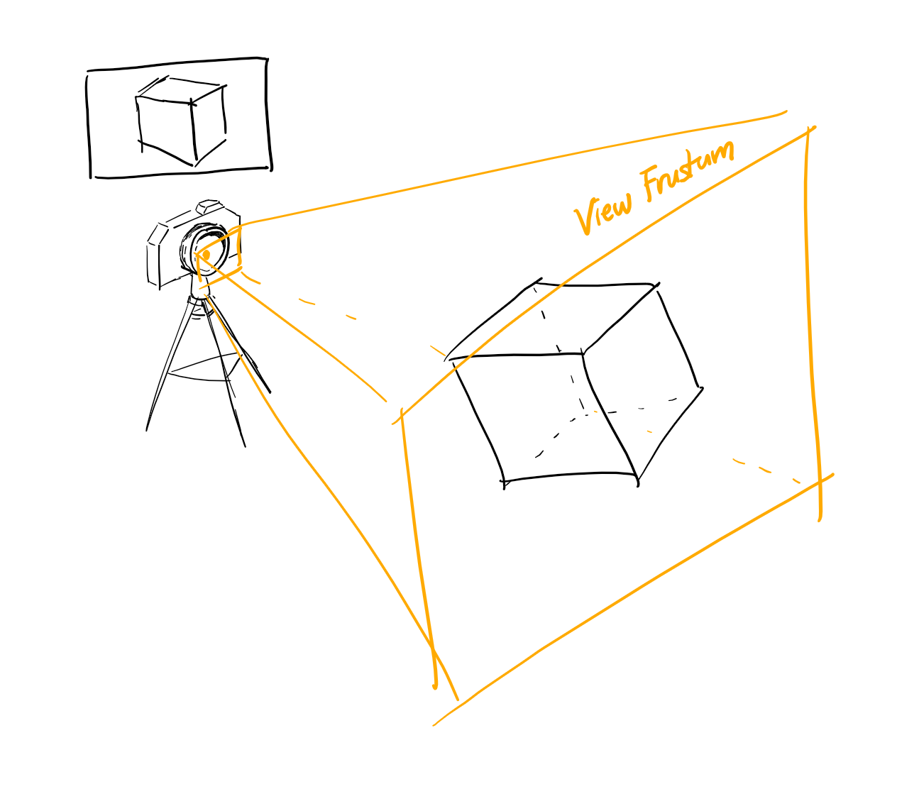
가상 카메라
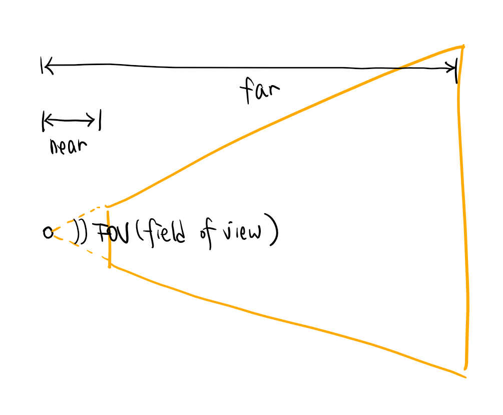
가상 카메라는 다음과 같은 property를 가지고 있습니다.
near: 화면에 보이는 물체가 카메라로부터 떨어져 있을 수 있는 최소 거리.far: 화면에 보이는 물체가 카메라로부터 떨어져 있을 수 있는 최대 거리.fov(field of view): 카메라의 너비aspectRatio: 화면의 가로-세로 비율.
이 수치들을 바탕으로 물체의 좌표계를 카메라의 좌표계로 변환하는 행렬(Projection Matrix)을 계산합니다. 여기에서는 자세한 수학은 생략하고, NPM 모듈 gl-matrix의 built-in 함수를 사용합니다. 어떠한 원리로 projection matrix가 만들어지는지 궁금하신 분들은 아래 링크들을 참조하시면 되겠습니다.
Wikipedia - Projection (Linear Algebra)
OpenGL Tutorial - Matrices
mat4.perspective(out, fov, aspectRatio, near, far);
가상 카메라를 구현하는 클래스 Camera를 engine/components/Camera.ts에 작성합니다.
import { mat4 } from 'gl-matrix';

export default class Camera {

    _near: number;
    _far: number;
    _fov: number;
    _aspectRatio: number;
    _projection: mat4;
    _updated: boolean;

    constructor() {
        this._near = 0.1;
        this._far  = 120.0;
        this._fov  = 0.5 * Math.PI;
        this._aspectRatio = 1.33;
        this._projection = mat4.create();
        this._updated = true;
    }

    getProjection(): mat4 {
        if (this._updated) {
            mat4.perspective(this._projection, this._fov, this._aspectRatio, this._near, this._far);
            this._updated = false;
        }
        return this._projection;
    }

    getNear(): number { return this._near; }
    setNear(near: number) { this._near = near; this._updated = true; }

    getFar(): number { return this._far; }
    setFar(far: number) { this._far = far; this._updated = true; }

    getFOV(): number { return this._fov; }
    setFOV(fov: number) { this._fov = fov; this._updated = true; }

    getAspectRatio(): number { return this._aspectRatio; }
    setAspectRatio(aspectRatio: number) { this._aspectRatio = aspectRatio; this._updated = true; }

}
Shader에서 Projection 사용하기
이전 튜토리얼에서 물체의 위치를 바꾸고 싶을 때, vertex의 좌표 벡터와 변환행렬을 곱해 vertex 위치를 얻을 수 있었습니다. 이제 가상 카메라의 위치와 방향, projection matrix를 함께 고려해 봅시다.
모델 내에서의 vertex 좌표에 모델 자체의 transformation을 적용하면 기준 좌표(world coordinate)에서 vertex의 좌표를 알 수 있습니다. (마치 직사각형이 x=0.3 위치에 있으면, 직사각형 모델의 (0.5, 0.5)가 (0.8, 0.5)로 변하는 것이죠.) 즉, 모델의 transformation은 model coordinate를 world coordinate로 변환합니다. 반대로, 모델의 inverse transformation(역행렬)은 world coordinate를 model coordinate로 변환합니다. 따라서, world coordinate 좌표에 카메라의 inverse transform을 적용하면, 카메라 좌표계에서 그 vertex의 좌표를 얻을 수 있습니다.
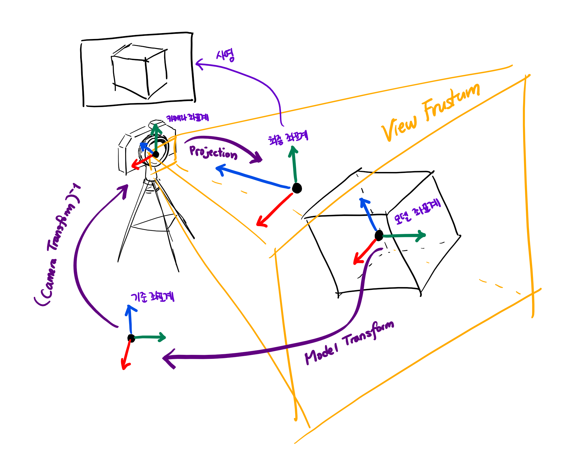
카메라 좌표계로 vertex를 나타낸 후, projection을 적용해 최종 좌표를 얻습니다. 정리하면, vertex의 좌표 벡터에 모델의 transformation, 카메라의 inverse transformation, 카메라의 projection을 차례로 곱해 나온 좌표를 화면에 표시합니다.
…
원리는 이렇지만, 사실 마지막 문장만 알면 코드를 작성하는 데 충분합니다. 필요한 행렬들을 uniform variable로 넘겨주고, engine/shaders/DefaultShader.ts의 vertex shader를 다음과 같이 바꾸세요.
#version 300 es

layout(location = 0) in vec3 position;
layout(location = 1) in vec2 uv;

uniform mat4 transformation;
uniform mat4 inverseCameraTransformation;
uniform mat4 projection;

out vec2 pass_uv;

void main() {
    gl_Position = projection * inverseCameraTransformation * transformation * vec4(position, 1);
    pass_uv = uv;
}
이제 어플리케이션에서 카메라와 카메라의 Transform을 정의하고, shader에서 카메라를 사용하도록 해 봅시다.
// src/main.ts

...
const camera = new Camera();
const cameraTransform = new Transform();
cameraTransform.setPosition(vec3.fromValues(0, 0, 3));
...
카메라는 기본적으로 (0, 0, 0) 위치에서 -z축을 바라보고 있습니다. 우리가 표시할 물체는 원점에 있으니까, 카메라를 (0, 0, 3)으로 옮겨 물체를 바라보도록 합니다. 그리고 렌더링 루프에서 카메라의 inverse transform과 projection을 매 프레임마다 넘겨줍니다.
// src/main.ts

...
mesh.start();
material.start(defaultShader);
defaultShader.setUniformMatrix4fv('transformation', transform.getLocalTransform());
defaultShader.setUniformMatrix4fv('inverseCameraTransformation',
    mat4.invert(mat4.create(), cameraTransform.getLocalTransform()));
defaultShader.setUniformMatrix4fv('projection', camera.getProjection());

mesh.render();

mesh.stop();
material.stop(defaultShader);
...
정육면체 모델
지금 우리가 가지고 있는 모델은 사각형 모델 뿐인데, 사각형은 평면도형이라 3D scene에서 보기에는 지루하니 정육면체 모델을 새로 만들어 표시해 봅시다.
mesh.updateVertexBuffer(new Float32Array([
    -0.5, -0.5, -0.5,   0, 0,
     0.5, -0.5, -0.5,   1, 0,
    -0.5,  0.5, -0.5,   0, 1,
     0.5,  0.5, -0.5,   1, 1,
    -0.5, -0.5,  0.5,   0, 1,
     0.5, -0.5,  0.5,   1, 1,
    -0.5,  0.5,  0.5,   0, 0,
     0.5,  0.5,  0.5,   1, 0,
    -0.5, -0.5,  0.5,   1, 0,
    -0.5,  0.5,  0.5,   1, 1,
     0.5, -0.5,  0.5,   0, 0,
     0.5,  0.5,  0.5,   0, 1,
]));
mesh.updateIndexBuffer(new Uint32Array([
    0,  3,  1,  0,  2,  3,
    0,  1,  5,  0,  5,  4,
    4,  5,  7,  4,  7,  6,
    2,  6,  7,  2,  7,  3,
    0,  9,  2,  0,  8,  9,
    1, 11, 10,  1,  3, 11,
]));
mesh.configure([[gl.FLOAT, 3], [gl.FLOAT, 2]]);
mesh.setCount(36);
그리고 대충 돌려주는 애니메이션을 적용해서 입체도형인 것을 잘 볼 수 있도록 합시다.
...
let prevTime = 0;
...
const mainLoop = (time: number) => {
    ...
    /* Handle animation. */
    const deltaTime = time - prevTime;
    prevTime = time;
    transform.rotateEulerX(0.001 * deltaTime);
    transform.rotateEulerY(0.001 * deltaTime);
    transform.rotateEulerZ(0.001 * deltaTime);
    ...
}
결과
드디어 3D 물체를 화면 상에 표시할 수 있게 되었습니다!
문제: Preview에서 정육면체가 앞뒤로 움직이는 것처럼 보이는데, 실제로는 정육면체의 위치는 변하지 않습니다. 카메라 설정을 변경하여 이러한 효과를 연출해 보세요.